Instructions for all products are on this page
ANSI 12″ Lock Display
WARNING – Do not ship this mount (to a trade show for example) with the hardware installed unless you use a LOT of cushioning.
Assembly Steps
- Lay all the parts out on a clean work surface with the finished (shiney) side up.
- Stack the 2 square bases on top of each other making sure the slots are aligned.
- Insert the tab from one edge piece into one of the small slots on the base with the finished side facing out. Press it all the way down through both base plates.
- Repeat for the other side.
- Insert a side panel into the long slot, shiney side facing out, slots facing in, and at a slight angle.
- Tilt it up and press it all the way down and align the tabs on the edge pieces with the slots in the side panel.
- Repeat for the other side.
- Install a rubber band at the top to hold it together until the hardware is installed.
Notes:
- Glue can be used anywhere tabs meet slots for a permanent build. 4 drops in the corners of the base plates will stop them from separating.
- Any wood glue such as TightBond or Elmers can be used (PVA (Polyvinyl Acetate)).
- I don’t recommend the polyurethane “Gorilla Glue” because it requires moisture to cure, and it expands requiring cleanup. Super Glues would also be quite messy.
- HOWEVER – one of the major design features is that the display stays together when hardware is installed so it really doesn’t need glue unless it is handled a lot.
- DONT GLUE the edges and side panels if you plan to create your own sales messages – see the Sales Techniques page.
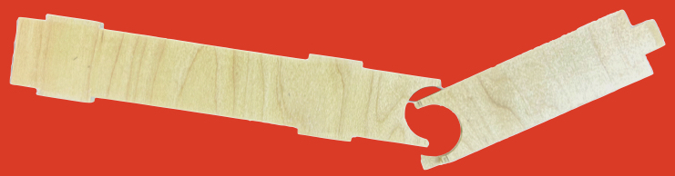
Warning
Do NOT apply any bending force to this part! It WILL break as shown.
Safe Cover Ups
INSTRUCTIONS
Square Cover Plate
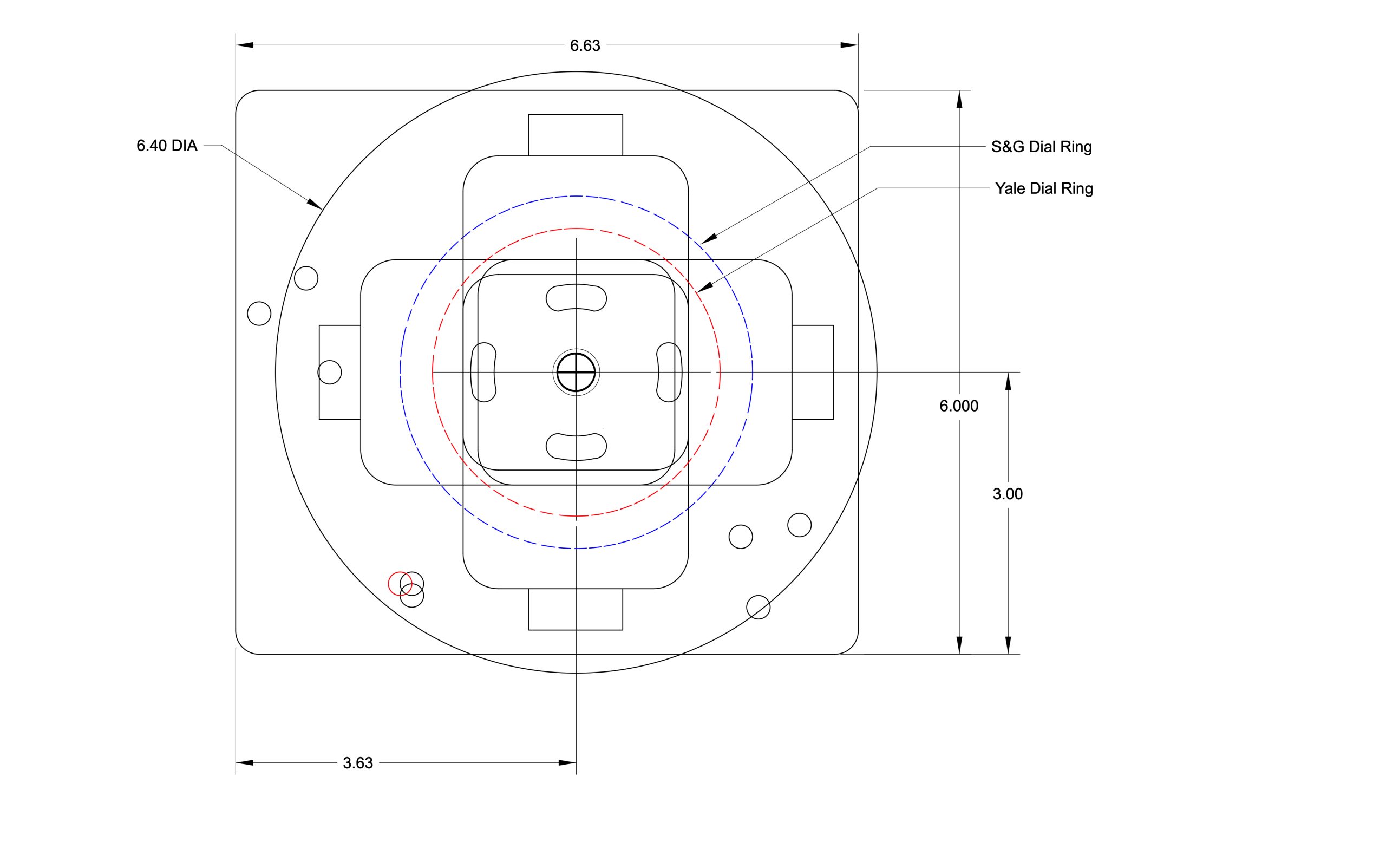
The square cover plate is actually rectangular. The dial center is offset in the plate. It was designed this way so that the “long side” of the plate can be positioned to cover a typical cam punch hole on safes such as Mosler or Meilink. It can be rotated 180 to cover left or right. You can also use it “vertical up” or down, but you might need to modify the dial ring holes. (V2 will fix that).
NOTE: The Dial ring holes are set for standard footprint locks such as S&G, Lagard, etc. If you need another hole pattern, LET ME KNOW, via email, or by using the contact form.
Round Cover Plate
This plate does not need any special instructions.
Drilled hole coverage map
The drawing shows the round plate and the square plate superimposed over each other along with some of the popular drill and punch hole locations that will be covered by the plates.
Fixing minor scratches in safe cover plates.
See this article on the BLOG page
Cylindrical Lock “Viewport”
This product really doesn’t need any special instruction. Simply install any cylindrical deadbolt or latch lock in the tube.
See this page for how to use this product in “Tactile Selling”.
Viewport for Mortise Locks
When using this product DON’T USE the cover screws that came with your lock. They have countersunk heads, which are wedge-shaped, and using them will crack the plastic when tightened. Purchase a few pan head screws instead. The size is usually 1/2″ x 8-32.